Developing a simulation and control system for an underwater robotic manipulator
This was a group project done in the Vibration Lab in IIT Jodhpur, Rajasthan, India under the guidance of Prof. Barun Pratiher and Nithin Tripathi
Team Members: Rishika Bera, Vellore Sahithi
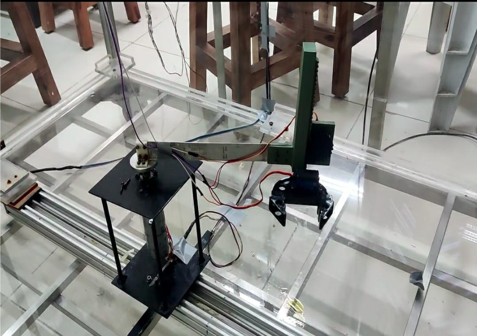
This project focuses on building a simulation and control system for an underwater robotic arm designed to pick and place objects in submerged environments. The system combines servo motors, a gripper, encoders, and path-planning algorithms to achieve accurate and reliable object handling. A rack and pinion mechanism is used for vertical motion, and the whole setup was tested using both physical hardware and Simulink simulations.
How the gripper works
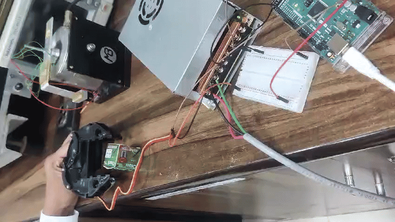
The gripper is controlled using a stator motor. The linear displacement of the gripper depends on the angle of rotation of the motor. A min angle is set for grasping the object and a maximum angle is set for releasing the object. The gripper was set such that there is a delay of few seconds after it grasps the object and drops it at the designated location. It was observed for every 10 degrees the gripper moves linearly by 0.5cm
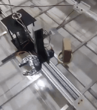
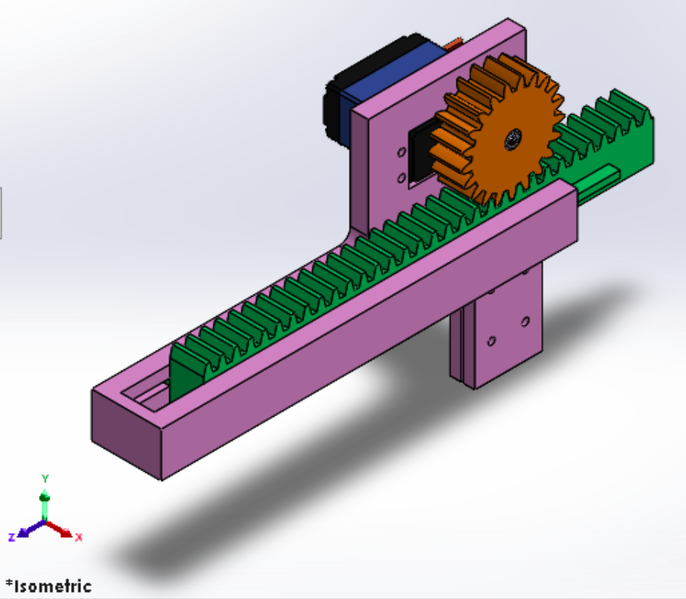
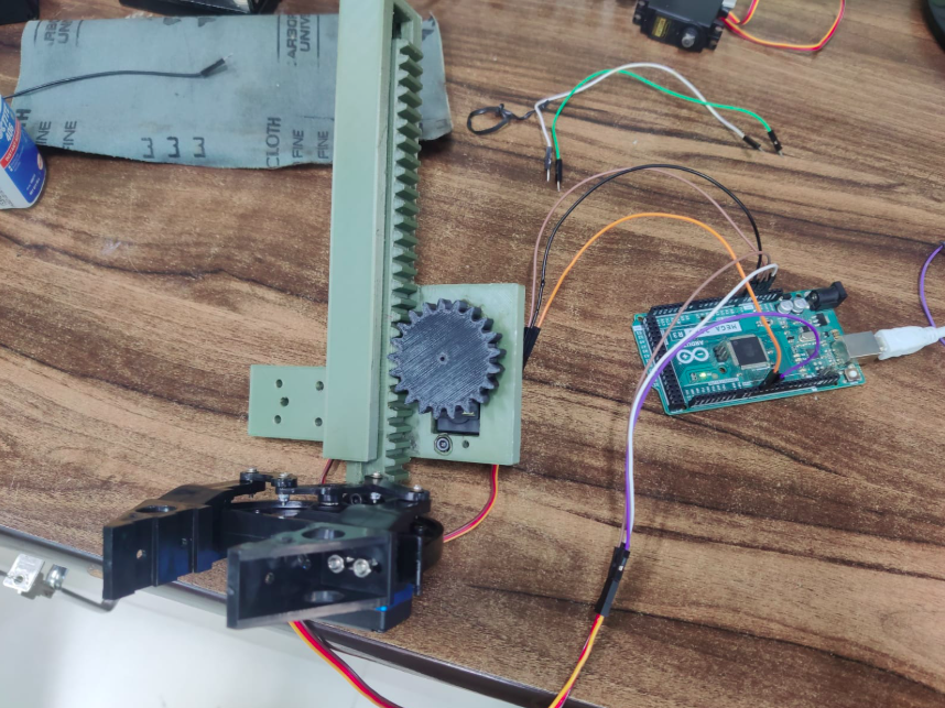
Rack and Pinion setup
A rack and pinion setup is used to move the gripper up and down. The servo motor rotates the pinion, which drives the rack in a straight line. Since the gripper is attached to the rack, it moves vertically based on the motor’s rotation, allowing it to align with objects at different heights.
Encoder
- Motor 1 uses an incremental optical encoder, which produces pulses as the motor rotates. These pulses help measure the motor’s position and speed accurately.
- Motor 2 uses a Hall-effect encoder, which detects magnetic field changes from the rotating shaft to determine speed and direction, making it reliable for underwater use.
Mounting the gripper
The gripper is mounted on the first link of the manipulator due to weight constraints. The final setup includes the encoder linked to the first link and then to the rack and pinion casing. The end effector is attached at the end of the rack.
Final Demo